
Stage 1 - Refurbishment & Repairs
Preface
Before we dive into how this project came together, I think a few words need to be said about the 4’ model in general.
The 4’ filming model of the Enterprise D has long been regarded by a lot of fans as the “ugly sister” to the larger, sleeker 6’ model built by ILM, and has earned the undeserved (in my opinion) title of “The Bulldog”. Common complaints about the 4’ model mostly stem from the slightly stockier overall shapes of the hulls, the shape of the deflector maw, and the overly pronounced hull plating. Other issues that are sometimes voiced relate to the overall execution of the model - that it isn’t as refined and well-built as the 6’ model, suffers from some noticeable asymmetries, visible seams around some of the armature access panels, and general wonkiness. All of these observations are true to some extent, there’s no denying that, but I think the model has been given a bit of an unfair shake over the years and I’d like to set at least some of that straight, if possible.
Some of the “problems” with the model stem from intentional design choices, such as the need to increase the saucer rim height and change the windows of Ten Forward to match those of the full-size set, or to add visual interest and scale by increasing the level of surface detailing with the raised plating and scribed panel lines all over the model. Whether or not those design choices were the right way to go, and if they achieved their intended goal or not, are a subjective thing. I might be in the minority here, but I quite like the hull plating! Some of the other “problems” stem from the extremely tight timescale and far lower budget available to get the model built. Greg Jein and his team (including Gary Hutzel, Dave Chamberlain, Dana White, Scott Schneider, Ed Miarecki, David Merriman, Christian Colquhoun, David Takemura, and Mike Okuda) were able to sculpt and detail the pattern masters from scratch, make the moulds, cast the fibreglass parts, fabricate the armature, assemble the parts around the armature, design and install the complex lighting system, do all the necessary construction and body work, do all of the complex paint work and weathering, apply the hull graphics, and deliver the finished model to the motion control stage at Image G in a matter of only a few weeks. Not months….WEEKS! Compare that to the 3 months ILM were given to build the 6-footer, along with an undoubtedly larger budget, and you can start to understand why the execution of the 4-footer might’ve been relatively lacking in some respects. The sheer amount of work required, and the speed at which they had to get it all done, is absolutely staggering! To all those mentioned above, and any I’ve undoubtedly missed, my hat is well and truly off to you!
I sincerely hope that after seeing how this project came together, and all of the work involved in a project like this, some of those long-standing complaints about “The Bulldog” can be forgiven. It’s about time that the 4’ model, and Greg’s team, finally get at least some of the respect and appreciation they deserve. It’s long overdue!
OK. Here we go then….
The raw parts
It probably goes without saying, but I’ll say it anyway – working with a set of casts that came from the same moulds that produced the filming model was a big deal. These casts were pulled from those production moulds 30-odd years years before the museum procured them, and what their journey was between then and being in my hands is not known to me. It’s been suggested that they could’ve been a set of “pyrotechnic” casts that were made in case they needed to have the Enterprise, or other Galaxy class ship, destroyed in an episode. I’m pretty certain that isn’t the case though. I’ve seen photos of pyro casts of the 4’ model that were used in the show, and those were cast in a green tooling resin called Dyna-Cast and were intentionally quite brittle and fragile. The parts the museum had procured were quite robust and were cast in fibreglass, most likely polyester based, and would’ve taken a LOT of effort to destroy on camera. From speaking to a couple of people who knew and worked with Greg Jein at the time, I’m told these were actually the very last parts that were cast, while Greg was “burning out” the moulds before they were disposed of. Judging by the obvious issues imparted by the poor condition of the moulds at the time these were cast, that certainly seems accurate to me and I believe this is the case.
Over the 30+ years since they were pulled from their moulds, they had been relatively well looked after and hadn’t suffered any significant damages or warping, no pun intended. It was very clear though, that the moulds were at the end of their serviceable life at the time these were cast. Some large chunks of pale blue silicone rubber were still lodged in the recessed sensor band around the upper saucer cast, and large chunks of fibreglass gelcoat were present where chunks of the mould had torn out in previous castings. The moulds also seem to have been stored in less-than-ideal conditions back then, as a couple of the casts had some strange rock-like protrusions and other strange distortions on them, almost as if some rubble and junk had been left laying in the empty moulds and had imparted deep impressions in the rubber, which were then transferred to the subsequent casts. The lower saucer cast was the worst affected by these distortions and needed the most amount of repair work to return it to its proper condition. The secondary/engineering/stardrive hull was cast in three separate parts – keel plate, underside of the pylon wing, and entire upper side of the hull (which also included the dorsal hull) all as one piece. Casting the entire upper part in one large piece saves a lot of time and effort later down the road during actual construction of the model, but it caused more than a few problems when it came to moulding and casting the part in the first place. Its complex shape meant that a two-part mould was needed so a section of the mould could be removed separately from the rest, which would then allow the cast to be released. This resulted in two visible seam lines on the cast where the mould parts joined each other - one running up the bow of the dorsal, and one travelling down the starboard edge of the dorsal and roughly along a gridline on the upper hull, towards the pylon wing. This particular seam is actually visible on-screen in some episodes, but I had never noticed it until now! Greg Jein clearly knew it wouldn’t be seen by most viewers, so didn’t waste time he didn’t have fixing it! The mould sections were obviously misaligned or getting very tired and no longer fitted together properly when this particular cast was made, as the seams were quite significant and there was some misalignment along the leading edge of the dorsal hull. Some of the raised surface relief and detailing was also quite deteriorated, another possible sign that the mould was starting to get very tired, particularly around the front quarters of the upper secondary hull part. All of these issues, as well as many other less drastic ones across all of the casts, would need to be addressed and fixed. So, it was decided that rather than build the model using these parts, they would be repaired and restored as accurately as possible, then moulded, and new casts made to build the actual replica. The original casts could then be preserved in their refurbished “raw” states in the museum archive. At the time of starting the project the museum only had casts of the saucer and secondary hull, not enough to build a complete replica. The plan was to attempt to locate original casts of all the missing parts (nacelles, deflector dish, bridge module, and saucer impulse engines) but proceed on the assumption that temporary parts would be fabricated to act as placeholders until originals could be found. Thanks to the great generosity of a few people, original casts for all those missing parts were gradually found, and the replica was eventually made entirely of original casts.
Clearly, a LOT of work lay ahead to get these parts faithfully and accurately repaired and restored, and ready for moulding.

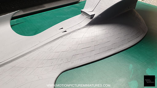
A scar from the mould mis-alignment can be seen quite clearly here

Another scar from the mould mis-alignment,
running through the leading edge of the dorsal hull

Proving the authenticity of the casts, the same scars can be seen on-screen in many of the effects shots featuring the original 4' filming miniature
I took literally HUNDREDS of photos to survey the raw casts before any work was done to them, to reference later if needed. What you're seeing below is a few examples that show exactly how they were when Greg Jein pulled them out of the original moulds decades ago. Crunchy physical features, rough and uneven window shapes, primer grain, hand-sculpted phaser strips...it's all there, baked right into the casts. You can even see pick marks in the large saucer windows, where the underlying foam was dinged whilst the window masks were pulled up through all the accumulated layers of paint, when the master patterns were originally made.
This is exactly how the actual 4' filming model looks when you get really close to it, but that was part of Greg's knowledge and experience - he knew that once the model was built, painted, filmed, and the final effects shots were finished, none of that stuff would show on TV screens.
The casts I got from the museum needed a lot of work to get them as close to "original" condition as possible, and this is that "original" condition. Not pristine. Not perfect. Certainly not symmetrical. I won't lie, it was very difficult to resist cleaning up all the crunchyness, and straightening up crooked lines etc, but that wouldn't have been a true representation of how the filming model ACTUALLY is.

Sensor band recess on the upper saucer part. Remnants of the original RTV rubber mould still lodged in place!

Aside from some slight general warping and wear & tear, the upper saucer was in pretty good shape.


Some examples of the deformations and damages on the lower saucer part. This part was in the worst condition by far and needed a lot of work to repair all of the issues. A lot of surface details needed to be repaired, or totally recreated in some cases, as close to original as possible.


Nine Forward windows. Not Ten Forward, that was below the sensor band, remember....oh, and some fragments of the original mould rubber still lodged in the sensor band, torn out when this part was demoulded decades ago!
Lower saucer windows. Different shape compared to the 6' filming model counter-parts. You can really see the various paint layers, all the way down to the underlying foam form in the windows...along with some visible pick marks left in the window recesses from when the masks were pulled up through all those paint layers.


Torpedo launcher deck. Clearly an insert part that was chopped into the foam form of the dorsal hull - you can see a subtle depression around the outer rim of the insert.
Aft phaser strips. Clearly hand sculpted originally, in clay most likely.
Fixing the various problems was going to inevitably require actually causing more damage and destruction to the casts, particularly when it came to tackling those rock-like protrusions. There was just no way to deal with those other than grinding and sanding them down, then recreating the detailing and layers of “plating” in some way. Maintaining accuracy and authenticity was absolutely paramount, so, before anything was done, a complete photographic survey was taken of all the casts, and every detail was captured and recorded. In order to accurately replicate all the scribed lines and raised panels that had been distorted by those rocky protrusions, masking tape was carefully applied to them, and surface rubbings and tracings were taken. The strips of tape were then removed, carefully applied to sheets of paper, and then scanned into the computer. Those scans could then be used as extremely accurate reference when it came to recreating the layered panelling and re-scribing any panel lines later on. This method was also used in areas where existing detailing and surface relief was in bad shape, as a result of the moulds being “burnt out”. Most of the remaining issues, like pin holes, cracks, and voids etc, would be addressed by the usual fill/sand/prime routine.


Some examples of the surface rubbings and tracings taken from the upper secondary hull and lower saucer parts. 14 sheets of A4 paper were eventually used for all the required tracings of the various parts
Once I was absolutely sure I had captured and recorded as much reference as I possibly could, the next step was to clean off any layers of primer that had already been applied to the casts at some point in their past, and to see exactly what I was dealing with underneath. The keel plate, lower pylon wing, and saucer parts yielded no big surprises and were basically untouched, other than being trimmed of any excess casting material and a little general clean up. The upper secondary hull, though, had obviously been worked on at some point in it’s past. There were a few spots of sanding drum damage from overly aggressive grinding away of excess material, and removing the black primer revealed quite a few visible areas where polyester body filler had been used to fill in and resculpt some voids that were present when the cast was originally made. I have no idea where this cast went in the intervening years, or who might’ve crossed paths with it, but I kind of like the thought that Greg Jein himself had started picking at it for some reason, but eventually put it to one side. Wishful thinking on my part perhaps, but whoever it was who started that work, it was now my responsibility to finish it!
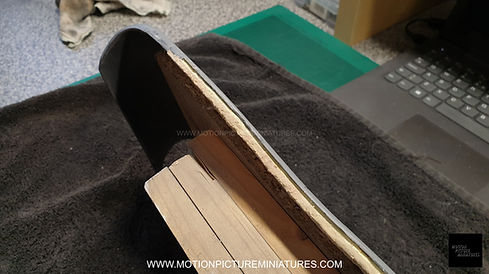
The first (and by far most nerve-wracking!) issues to fix were those two glaringly apparent seams, and there was really only one way to tackle them…by cutting through the seams, re-aligning the surfaces, and gluing them back into their correctly aligned positions. Or, as close as they would allow, at least. A very thin disc cutter on a Dremel was used to slit the first inch or two of the rear seam where the adjacent surfaces were off-set height-wise, and the entire seam running up the leading edge of the dorsal was cut through. All the mis-aligned surfaces were carefully re-aligned as well as they would allow, glued into position, and backed with extra epoxy resin. There was no way to correct the misalignment at the very front of the flared out “cobra head”, so a small area was filled with epoxy putty as a compromise, to a least even it all out. All the gaps along the newly aligned seams were then filled with polyester body filler and/or modelling putty and refined over many passes of application and sanding. Eventually, the original shapes and contours were restored as closely as I could manage, but a fair amount of detail had been destroyed from the repeated sanding and body filler application. Window recesses, grid lines, raised panelling, scribed panel lines…they all needed to be reproduced exactly as they were before. This is where all those surface tracings and photo surveys came into service. I didn’t realise it at the time, but the method I used to reproduce the lost details was the same one Scott Schneider used to detail the original pattern masters of the parts a few decades earlier!


Multiple passes of applying body filler, sanding and reshaping, priming, more sanding etc, were needed to
get everything as straightened out as they could be. Some details were inevitably lost in this process, and
would need to be recreated exactly
In a conversation I had with Scott, he confirmed that the original patterns were made of 6lb foam, skinned with Bondo (a type of car body filler) and sanded smooth. After a coat or two of primer, guidelines for all the major details (like gridline positions, hatches, panels etc) were scribed into the surface, and thousands of window shaped pieces of vinyl were applied all over the patterns. A few more coats of high-build primer were then applied to build up some thickness over the parts, sealing in the vinyl window shapes. The surfaces were then covered with Frisket film (an artist’s vinyl-like masking/stencil making material), and the complex “Aztec” plating was drawn directly onto them by Greg Jein. Those panels were then carefully cut in-situ by hand with a scalpel blade by Scott, and some of the shapes were then removed in an alternating pattern across the surface, leaving the complex “Aztec” plating design on the parts in Frisket film. Several more layers of primer were applied over the parts to build up even more paint thickness, and when cured, all the frisket stencils and vinyl window shapes were peeled up, leaving several layers of plating with varying thicknesses, and window recesses which cut through all the various layers down to the original surface of the pattern. The plating layers were then further broken up with thousands of hand scribed panel lines, the main grid lines were defined using very narrow vinyl tape (most likely Chartpak tape, commonly used on whiteboards) which were only a couple of millimetres thick, and hundreds of lifeboat cover hatches (Avery labels) were applied. Phaser strips and other final panel details were added, and the patterns were then moulded, and fibreglass casts made. Now, if that sounds like a lot of work, then let me tell you first-hand….IT IS! It’s this exact method I used to recreate those details on these casts. But I had the benefit of having an existing pattern to copy, and only needed to do so in certain areas, so most of the work had already been done for me in a sense. I also had the benefit of modern technology in the form of a vinyl cutter that could do all that laborious cutting for me, and do it far quicker than I could by hand. Scott, Greg, and the rest of the team who built the original did all that work, and much more, at lightning-fast pace…it still blows my mind thinking about it!
So, all those surface rubbings I had made earlier were scanned and imported into the cutting software, carefully traced and redrawn, and converted into cutting files that the vinyl cutter could use to create as many copies of the pattern as I might need, for all the areas on the various casts that would need it. I also created masks for all the varying window sizes and shapes, and a bunch of new lifeboat hatches that would be needed on the lower saucer cast. All of the lost windows, raised plating details, scribed panel lines, and raised grid lines were recreated using the same steps described above. This method was applied to all of the casts, and eventually, after several months of painstaking work, they were all restored as accurately as I could possibly get and were ready for moulding. The photos below show a small overview of some of that work, to give an indictation of what was done. I have hundreds more photos, far too many to show here...!


The Repaired and Refurbished Parts


COMING IN PART 2...
MOULDING AND CASTING THE PARTS...


